Background
What is DODAF?
The Department of Defense Architecture Framework (DODAF) is a comprehensive architecture framework developed by the U.S. Department of Defense to standardize the way complex systems and architectures are described, communicated, and analyzed. DODAF provides a common approach for organizing and presenting architecture descriptions to ensure consistency and interoperability across defense programs and initiatives.DODAF Version 2.02 is the current standard, though many organizations still reference earlier versions. The framework is structured around viewpoints that organize architectural data into meaningful perspectives for different stakeholders.
Why is DODAF Important?
DODAF serves several critical purposes in defense and systems engineering:- Standardization: Provides a common language for describing architectures across different programs, services, and organizations
- Interoperability: Ensures systems can work together by establishing clear interfaces and data exchanges
- Decision Support: Enables informed decision-making through structured analysis and visualization of complex systems
- Compliance: Required for many DoD acquisition programs and serves as a basis for architecture reviews and assessments
- Communication: Facilitates clear communication between stakeholders including engineers, program managers, operators, and leadership
- Lifecycle Management: Supports systems from concept through development, deployment, and sustainment
What is the OV-1?
The OV-1 (Operational View - High Level Operational Concept Graphic) is one of the most fundamental and widely-used DODAF products. It provides a high-level graphical/textual description of the operational concept, showing:- Mission Context: The overarching mission or operational scenario
- Operational Nodes: Organizations, command centers, or operational facilities involved
- Systems and Platforms: Major weapon systems, sensors, communications systems, and platforms
- Information Flows: Key information exchanges and command/control relationships
- Activities: Primary operational activities or tasks being performed
- Geographic Context: Sometimes includes operational areas or deployment locations
Examples of OV-1 Diagrams
OV-1 diagrams vary in style, complexity, and presentation depending on the program and operational context. Here are examples showing different approaches:.jpg?fit=max&auto=format&n=NFYZUPrBYtSXyxp2&q=85&s=82a65e3867cd35f61640b7c90adb3f63)
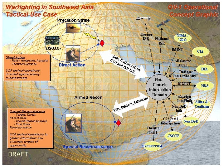
OV-1 diagrams can range from simple conceptual sketches to detailed, multi-layered operational graphics. Davinci can extract structured models from any of these styles, regardless of visual complexity or format.
Why is the OV-1 Important?
The OV-1 serves as the executive summary of an architecture:- First Impression: Often the first artifact stakeholders see; sets the context for all other views
- Stakeholder Communication: Designed to be understandable by both technical and non-technical audiences
- Concept Validation: Helps validate that all stakeholders share a common understanding of the operational concept
- Requirements Traceability: Establishes the operational context from which requirements flow
- Foundation for Detail: Provides the framework that more detailed views (OV-2, OV-5, SV-1, etc.) expand upon
- Briefing Tool: Frequently used in program reviews, capability assessments, and stakeholder briefings
Modeling in Davinci
Step 1: Upload Your OV-1 Diagram
To begin analyzing your OV-1 DODAF artifact:- Open the Davinci Webapp in your web browser
- Start a new Project or continue an existing one
- Upload your OV-1 diagram by:
- Clicking the upload/attachment icon in the chat input area, or
- Clicking the upload/attachment icon in the library section, or
- Dragging and dropping your image file directly into the chat
- Supported formats: PNG, JPG, JPEG, SVG, PDF
Step 2: Prompt Davinci
Once you’ve uploaded your OV-1 diagram, you can use various prompts to extract information and create structured models:Example Prompts
Create a Basic Parts Tree:Step 3: Review and Refine Results
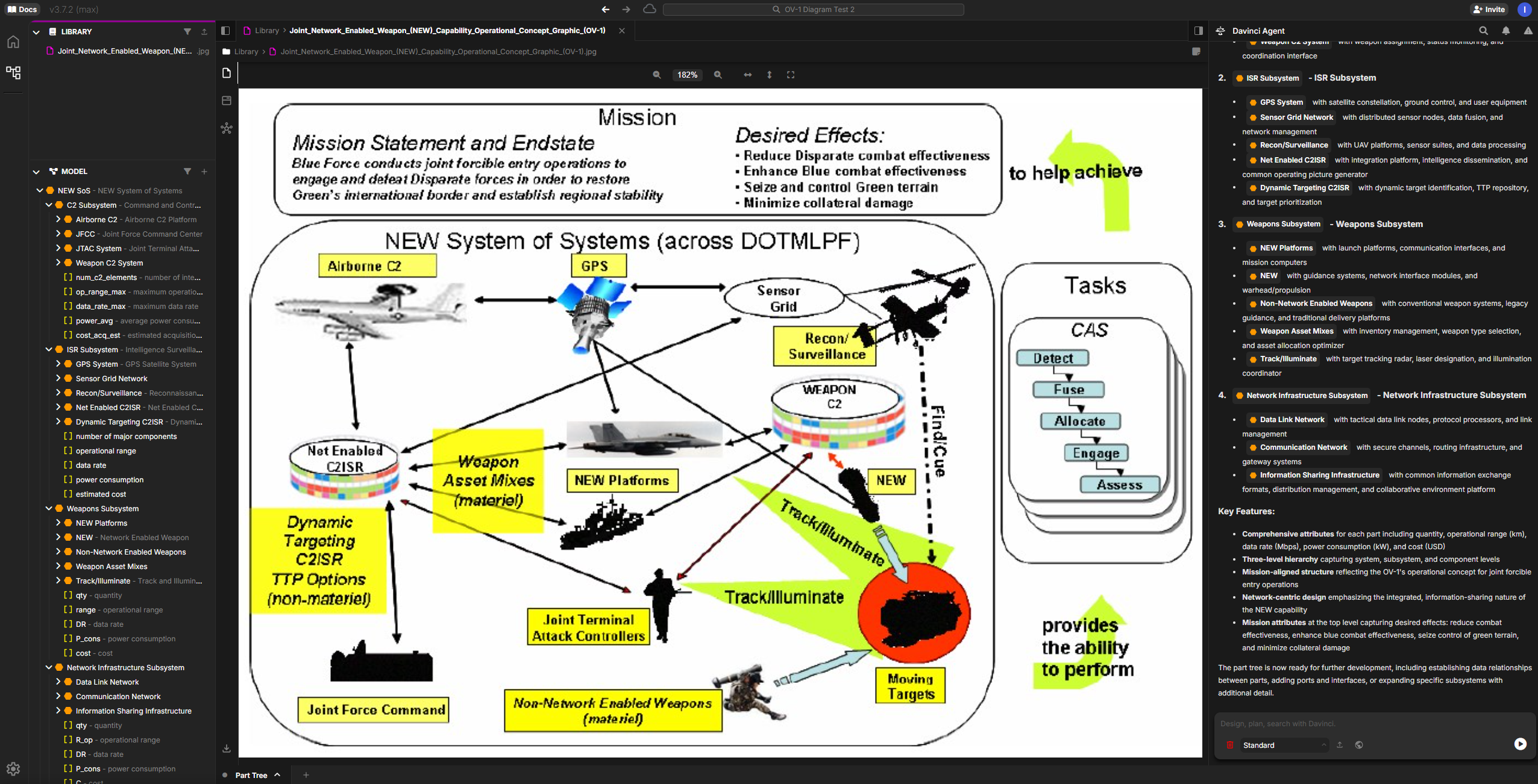
The Davinci will analyze your OV-1 diagram and provide structured results:What to Expect
1. Model Elements Created:- Parts: Logical pieces of systems or system of systems
- Requirements: Mission statements, operational objectives, desired effects
- Entities: Operational nodes, weapon systems, platforms, C2ISR components
- Actions: Operational tasks and activities (e.g., Detect, Fuse, Allocate, Engage, Assess)
- References: Relationships and information flows between components
- Documentation: Descriptions and context for each element
- Component hierarchies
- Task sequences
- System relationships
- Capability mappings
- Information exchanges between nodes
- Command and control relationships
- Data flows and dependencies
Refining the Results
You can iteratively improve the model by:Example Use Case
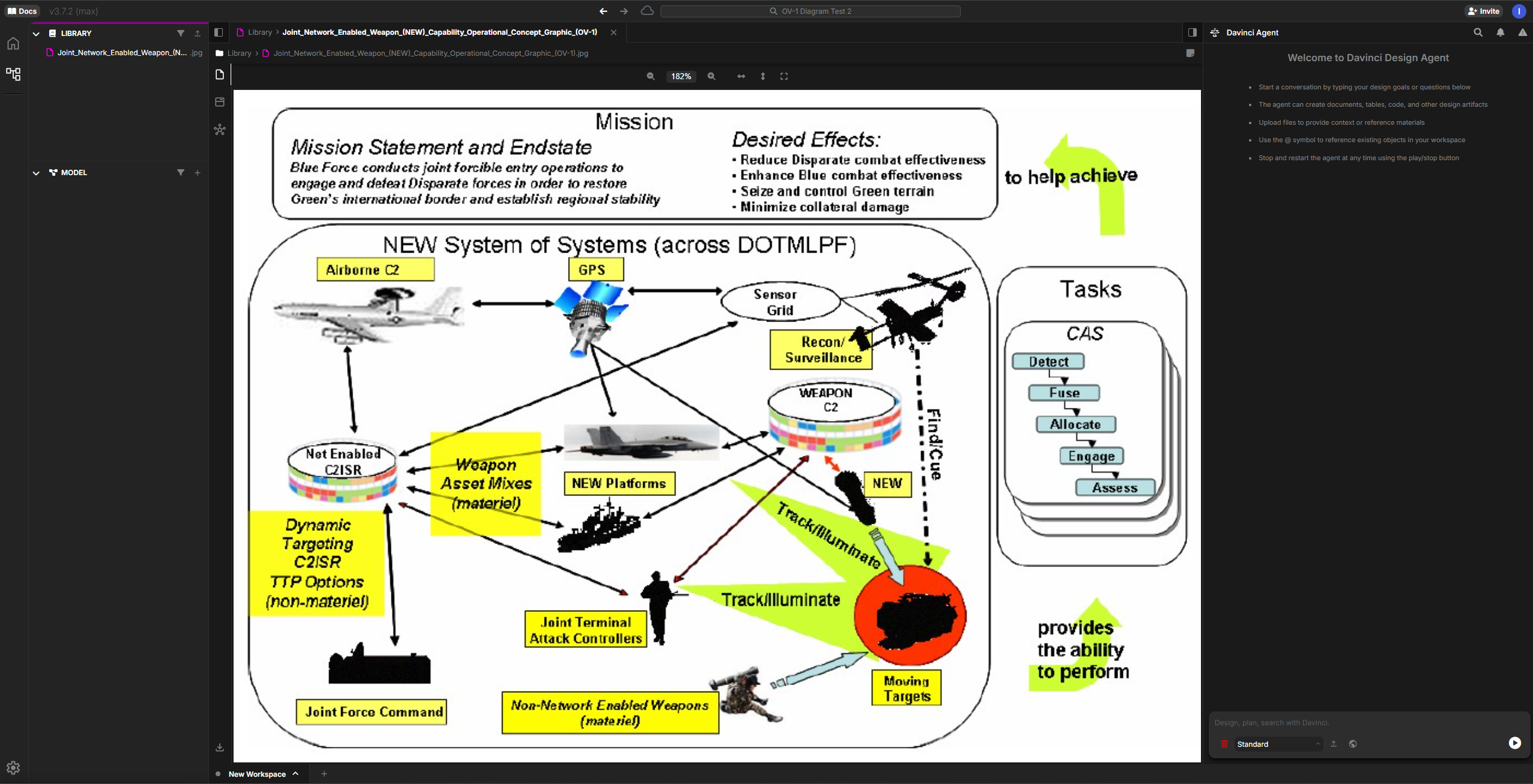
Consider an OV-1 diagram showing a Joint Network Enabled Weapon system with:- Mission: Blue Force conducts joint forcible entry operations
- Desired Effects: Reduce combat effectiveness, enhance blue combat effectiveness, seize/control terrain
- Operational Nodes: Airborne C2, GPS, Sensor Grid, Recon/Surveillance, Weapon systems
- Tasks: CAS operations (Detect, Fuse, Allocate, Engage, Assess)
Sample Interaction
Uploads OV-1 diagram and prompts: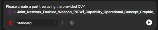
- Top-level system (Joint Network Enabled Weapon System)
- Major subsystems (Airborne C2, GPS, Sensor Grid, Recon/Surveillance, Weapon platforms, etc.)
- Component relationships reflecting the operational architecture
Why This Matters
Transforming OV-1 diagrams into structured Davinci models delivers critical value throughout the system lifecycle: Speed & Efficiency: What traditionally takes hours or days of manual transcription now happens in minutes. Systems engineers can rapidly convert legacy diagrams, proposal graphics, or stakeholder sketches into working models without tedious data entry. From Static to Dynamic: OV-1 diagrams are typically static images locked in PowerPoint or PDF files. Davinci transforms them into living, queryable models that can be analyzed, traced, versioned, and evolved as the architecture matures. Components become traceable objects with relationships, attributes, and requirements linkages. Early Program Acceleration: During critical early phases—concept development, Analysis of Alternatives, proposal response—teams need to rapidly iterate on architectural concepts. Davinci enables fast exploration of alternatives by quickly generating baseline models that stakeholders can refine and compare. Reduces Error & Rework: Manual transcription introduces errors and inconsistencies. Automated extraction from source artifacts ensures fidelity to the original diagram while creating a structured foundation that reduces costly rework later in the program lifecycle.Best Practices
Image Quality
Use high-resolution images with clear text and legible annotations
Context
Provide additional context about the operational scenario in your prompts
Iterative
Start with broad analysis, then refine specific components
Verification
Review generated elements against the source diagram for accuracy
Tips for Better Results
- Be Specific: Reference specific components or areas of the diagram in your prompts
- Break It Down: For complex diagrams, analyze sections independently
- Validate: Cross-check generated models against the source diagram
- Enhance: Add additional attributes and relationships not visible in the diagram
Next Steps
After creating your initial model from the OV-1:- Add Detail: Enhance entities with attributes, constraints, and detailed requirements
- Link Artifacts: Connect to other architectural views and documentation
- Generate Reports: Use Davinci’s export features to create deliverable documentation